| Product Name | Model Number |
| AMF (IOT Based SIS-AXS) | SIS25KVA-IN-AC1501 |
| AMF Panel (IOT Based SIS-AXS) | SIS40KVA-IN-AC1503 |
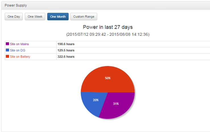
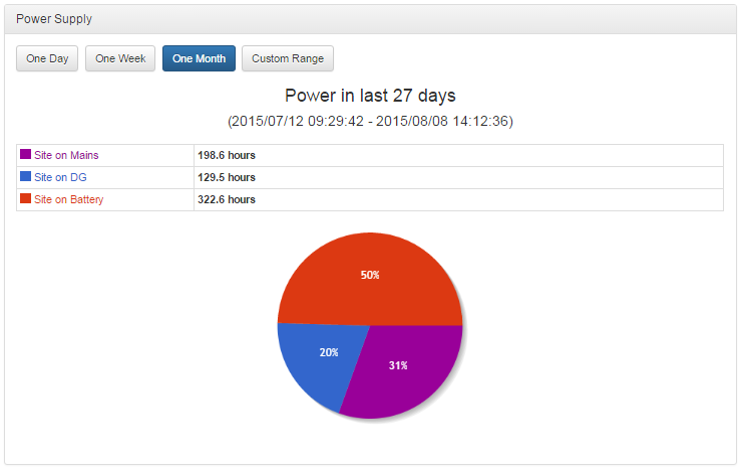
SIS-AXS Energy Status One Month
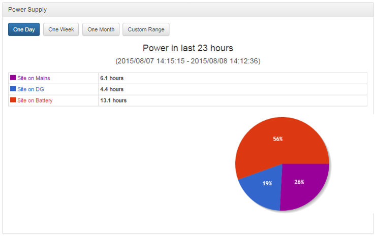
SIS-AXS Energy Status One Day
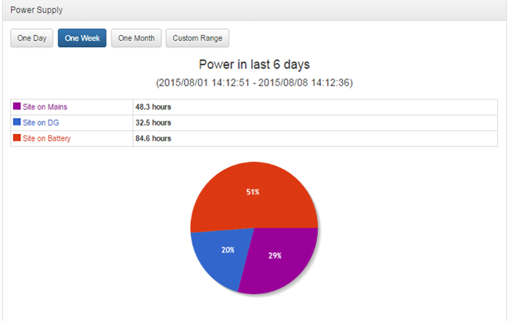
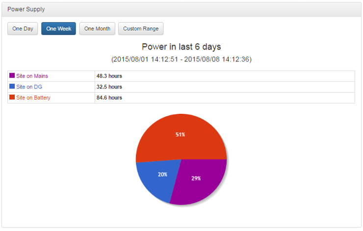
SIS-AXS Energy Status One Week
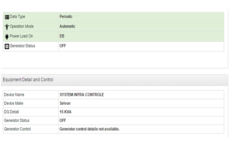
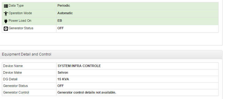
SIS-AXS Equipment Details
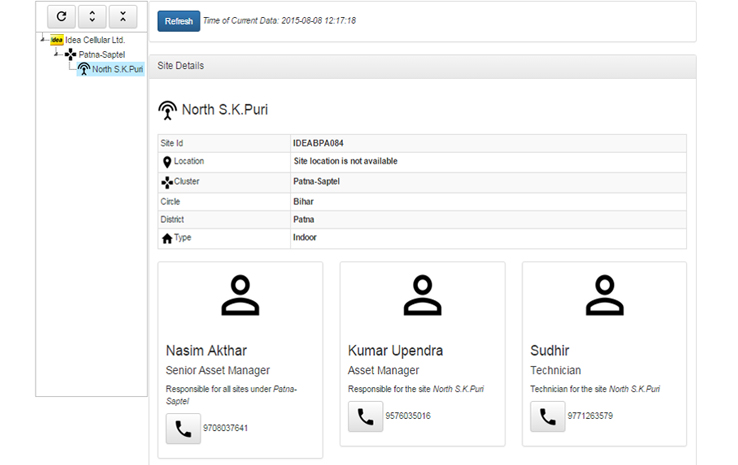
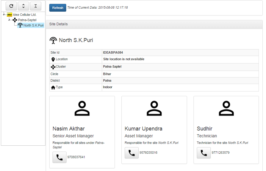
SIS-AXS Site Details
Introduction
SIS-AXS controller is an integrated multifunction high speed micro controller based System. It s having a provision of single phase/three phase mains and DG with Automatic /manual modes of operations. This controller includes protection for mains and DG (as per standards). This controller in having battery and room temperature monitoring facility.
System Controller system is designed for telecom sites it can used Like (PIU/IPMS/AMF). SISPL SIS-AXS controller unit has inbuilt Feature remote management, Energy Management and fault detection, power scalability, Etc. that enhance the fuel and battery efficiency in the existing sites. This controller follows a rational approach towards power management through
- Integrated AMF Function.
- AC power measurement.
- DG parameter monitoring.
- Alarm Consolidation.
- Remote monitoring facility.
The highlighting feature of SIS-AXS controller is that it reduces the operational costs through a well-researched fuel management system The fault management and functionality units of this system is adaptable for Air-conditioners, Batteries, Fire alarms, Diesel Gen sets, Security, AC Power, DC power, lightening and surge protection, etc.
Other feature:-
- AC distribution unit.
- Fire Alarm module.
- Aviation lamp controller.
- Auto phase Selector.
- IPMS logic.
- SVR controller.
- Real time and events recording.
- One/Two DG control.
- Configuration (almost fifty programmable parameters).
- Calibration (on site calibration facility for all analog parameter).
| Description | Standard Specification |
|---|---|
| Capacity | Range of 5 to 50 KVA |
| Multi Phase Logic | SIS-AXS controller will work on 1Phase, 2phase or 3Phase. Input voltage range on single phase – 145V–300V |
| Mechanical | CNC Fabricated box, using CRC Sheet duly powder coated, 1.6 mm thick CRC sheet. Split type modular design. |
| Safety | The equipment will ensure IEC 60950 safety standards |
| MTBF | All material & workmanship will be of professional quality to ensure MTBF requirement. The MTBF of the AMF controller is more than 70000 hrs. |
| Compliance | CE, Tested for safety, EMI/RFI compliance |
| Micro Controller | High-Speed micro controller True RMS for all voltage & current All the inputs to the measurement board will be duly protected against surge as per IEEE-62.41 The measurement circuit will be rated at least twice of the maximum input range, each independent for AMF & module |
| Time | Real time & date-programmable |
| Event Logs | Last 2000 events |
| RS 232t for SISPL use only | For PC interface to adjust the critical data and unload the alarms, This Port will be used for configuration of PFCs. |
| Energy | Will be able to measure the DG energy (Cumulative KWH & Hrs) Will be able to measure the EB energy (Cumulative KWH & Hrs) Will be able to measure the Battery energy (Cumulative KWH & Hrs) |
| Data Transfer | SIS-AXS controller will be equipped with suitable GPRS modem / GPRS DTU and able to process the data. |
| DG on load | After DG starts and supply is healthy |
| Blackout delay | 5 Seconds between mains and DG contactor changeover. |
| DG cooling time | 15 minutes |
| DG start attempts | Three attempts with delay between attempts ( 40 -40 -40 sec )(settable) |
| DG Lock time | After three very short mains restoration 10-10-20 minutes, DG will run for 1hrs (settable) continuously. |
| Stop Command duration | Settable from 10 to 50 seconds |
| Battery charger & DG controller unit | Automatic DG battery, SMPS charger with boost/trickle charging & with constant cur¬rent charging facility (12V) Provision of Auto manual mode selection |
| Auto Phase selector | The AMF Controller will be inbuilt with auto phase selector which will select any two phase or single phase out of 3 Phase. There will be a electrical and mechanical interlock between each contactor to avoid short circuit in case of electronic failure |
| Auto Phase selector | The AMF Controller will be inbuilt with auto phase selector which will select any two phase or single phase out of 3 Phase. There will be a electrical and mechanical interlock between each contactor to avoid short cir¬cuit in case of electronic failure |
| Set point-for high temperature alarm | Factory set (“ON” at 40°C and “OFF” at ON - 3°C) |
| DG set measurements | Mains/DG status, DG accumulated hours, DG voltage, DG Energy Measurement (DG KWH) |
| Mains measurements | Input Voltage, Output voltages for line conditioning module, Mains Energy Measurement (EB KWH) |
| Battery measurements | Battery running hrs & KWH (Accumulated) |
| LED Indications: | Mains ON, DG ON, Smoke/ Fire Alarm, DG Common Fault, Fuel Low, System battery low, High Shelter temperature |
| List of potential free dry contacts | Alarms will be extended to NOC / TOC through changeover contact (both ‘NO’, ‘NC’). Mains fail, Shelter Door open/ Intruder, Low fuel level, Common fault -- LLOP/Alt fault/HCT/HWT/V belt/Dg fail to start/DG fail to stop, Smoke/Fire, Load on DG, DG Fail to stop, DG Fail to start, DG over load, Shelter high temperature, Site on battery, BTS Battery Low. |
| Standard setting | Setting in the AMF Controller can change manually & Laptop. |
| Site Calibration | All measured parameter can you calibrate through S/W on field |
| Dual DG Logic | Will be provided the Dual dg logic on sequential basis. |
Configuration (Programmable Parameters)
The configuration for controller module is as follows:-
| S.NO | Parameter Name | Max Value | Min Value | Default Value |
|---|---|---|---|---|
| 1. | MAINS HIGH CUTOFF | 500 | 240 | 300 |
| 2. | MAINS LOW CUTOFF | 350 | 70 | 90 |
| 3. | MAINS HIGH CUTIN | 500 | 220 | 290 |
| 4. | MAINS LOW CUTIN | 360 | 70 | 130 |
| 5. | DG HIGH CUTOFF | 280 | 240 | 260 |
| 6. | DG LOW CUTOFF | 210 | 140 | 170 |
| 7. | DG RPM HIGH | 3000 | 1550 | 1650 |
| 8. | DG RPM LOW | 1500 | 1000 | 1350 |
| 9. | ROOM TMP.HIGH ALARM | 60 | 15 | 40 |
| 10. | DG CRANK TEMP HIGH | 60 | 15 | 35 |
| 11. | DG OVERLOAD | 150 | 1 | 35 |
| 12. | EB OVERLOAD | 150 | 1 | 35 |
| 13. | BTS BATTERY LOW | 60.0 | 20.0 | 47.0 |
| 14. | DG AUTO RUN TIME | 18 | 1 | 6 |
| 15. | CRANK ACTIVE TIME | 10 | 1 | 3 |
| 16. | CRANK RETRIES | 5 | 0 | 2 |
| 17. | STOP HOLD TIME | 50 | 10 | 30 |
| 18. | STOP RETRIES | 5 | 0 | 2 |
| 19. | DG WARM UP TIME | 90 | 10 | 10 |
| 20. | MAINS RESTORE TIME | 300 | 20 | 30 |
| 20. | DG COOL DOWN TIME | 900 | 30 | 60 |
| 21. | DG LOCK TIME | 150 | 10 | 10 |
| 22. | LLOP DELAY TIME | 50 | 5 | 5 |
| 23. | DG START INTERVAL | 240 | 30 | 40 |
| 24. | CT RATIO | 250 | 25 | 125 |
| 25. | LLOP ENABLE/DISABLE | DISABLE | ||
| 26. | EB FLUCTION TIME | 30 | 1 | 20 |
| 27. | EQUALIZE CHG NORMAL | DISABLE | ||
| 28. | EQUALIZE CHG MANUALLY | DISABLE | ||
| 29. | BATTERY CHARGE INTERVAL | 1440 | 1 | 168 |
| 30. | BATTERY CHARGE TIME | 48 | 1 | 12 |
| 31. | AVIATION ON TIME IN HOUR | 23 | 0 | 18 |
| 32. | AVIATION ON TIME IN MINUTE | 59 | 0 | 0 |
| 33. | AVIATION OFF TIME IN HOUR | 23 | 0 | 6 |
| 34. | AVIATION OFF TIME IN MINUTE | 59 | 0 | 0 |
| 35. | SVR HIGH CUTOFF | 300 | 240 | 260 |
| 36. | SVR LOW CUTOFF | 210 | 150 | 180 |
| 37. | PSEL ENABLE/DISABLE | ENABLE | ||
| 38. | PSEL HIGH CUT OFF | 300 | 240 | 300 |
| 39. | PSEL LOW CUT OFF | 180 | 70 | 90 |
| 40. | PSEL HIGH CUTIN | 290 | 250 | 280 |
| 41. | PSEL LOW CUTIN | 200 | 70 | 120 |
| 42. | PHASE UNBALANCE | 90 | 20 | 50 |
Calibration Parameter (The calibration parameters are as follows)
| S. No | Parameter name | Actual value | Measured value |
|---|---|---|---|
| 1. | Main R-PH Voltage | xxx | xxx |
| 2. | Main Y-PH Voltage | xxx | xxx |
| 3. | Main B-PH Voltage | xxx | xxx |
| 4. | LCU#1 Voltage | xxx | xxx |
| 5. | LCU#2 Voltage | xxx | xxx |
| 6. | LCU#3 Voltage | xxx | xxx |
| 7. | DG R-PH Voltage | xxx | xxx |
| 8. | DG Y-PH Voltage | xxx | xxx |
| 9. | DG B-PH Voltage | xxx | xxx |
| 10. | EB I/P current R-Phase | xxx | xxx |
| 11. | EB I/P current Y-Phase | xxx | xxx |
| 12. | EB I/P current B-Phase | xxx | xxx |
| 13. | O/P current R-Phase | xxx | xxx |
| 14. | O/P current Y-Phase | xxx | xxx |
| 15. | O/P current B-Phase | xxx | xxx |
| 16. | Room Temperature | xxx | xxx |
| 17. | Ambient Temperature | xxx | xxx |
| 18. | BTS Battery voltage | xxx | xxx |
| 19. | DG Battery voltage | xxx | xxx |
Actual values display what have you apply and measured value is measurement by controller.
Operation
The calibration parameters are as follows:-
- Key function
- Calibrations
- Configurations
- System Operation
Key Function
There are five switches in Display Board
- # SW1 for Increment and Reset
- # SW2 for Decrement and Scrolling
- # SW3 for Enter and Events
- # SW4 for Configuration
- # SW5 for Escape
#SW1:
This switch is used for two
purposes one for increment and other for system reset.
Normally this switch is working for system reset. When you go for configuration that
time this switch working for increment.
#SW2:
This switch is used for two purposes one for
decrement and other for display scrolling. Normally this switch is working for
display scrolling. When you go for configuration that time this switch working for
decrement.
#SW3:
This switch is used for two purposes one for
Enter and other for events log display. Normally this switch is working for events
log display. When you go for configuration that time this switch working for enters.
#SW4:
This switch is used for two purposes one for
Enter and other for events log display. Normally this switch is working for events
log display. When you go for configuration that time this switch working for enters.
#SW5:
This switch is used for escape. Purpose of
this switch in any stage you can go for default display.
Calibration
For any analog parameter calibration, you can go for calibration mode by configuration. In calibration mode you can go for that parameter which you want to calibrate. After you can set the value by increment and decrement key if actual value is equal to apply value press enter key and then press the escape key. And check that parameter is ok or not.
Configuration
For any programmable parameter changing you can go in menu setting by configuration mode. In configuration mode you can go for that parameter which you want to change after this you can adjust by increment and decrement key and then press enter key. Then go for escape.
System Operation
The operation of SIS-AXS controller in two ways on is AUTO mode and other is manual mode. In auto mode controller control the DG function automatically and check the DG alarm status but in manual mode no control the DG operation. In auto mode when mains or LCU voltage out of range or not available then check BTS battery voltage if BTS battery voltage is below of specified limit and room temperature is above limit, then check DG alarm status if no fault of DG after that check for LLOP if LLOP enable and connected properly and LED indication of LLOP should be off, if not then show in LCD display LLOP OPEN and not DG start. After checking the LLOP give the crank for DG start and wait for DG voltage if DG voltage is not coming within 30 seconds after given the crank, then give again crank for DG start and wait for DG voltage. If DG voltage is not coming after DG start the show DG fail to start and LED indication of fail to start should on. But if DG voltage is coming and within range then go for DG warm up otherwise generate the DG ALT fault. After DG warm upload is on and LCD display show DG OK. And check DG alarm like LLOP, Half FUEL, Low FUEL, HCT, overload, over speed. If any alarm generated, then give DG stop command. If DG is not stop after successful stop command, then show for DG fail to stop and LED indication of fail to start will on. If no alarm is generated and mains healthy that case DG will go for stop and after DG stop load will change on mains.
Alarm checking
1) Fail to stop
If DG is running and any DG fault is generated, or mains is restored then go for DG stop and after stop hold time DG is not stop then fail to stop alarm is generated. LED indication of fail to stop is continuing. Fail to stop and DG common fault relays will ON.
2) Fail to start
If DG crank is active and DG voltage is not coming within 30 seconds, then fail to start alarm is generated. LED indication of fail to start is continuing ON. Fail to start and DG common fault relays will ON.
3) LLOP Fault
If DG is running and LLOP sensing input is close, then LLOP fault is generated. LED indication of LLOP is continuing. LLOP and DG common fault relays will ON.
4) LOW FUEL
If DG is running and Low fuel sensing input is close, then Low fuel alarm is generated. LED indication of low fuel is continuing. Fuel relay will ON.
5) Half FUEL
If DG is running and half fuel sensing input is close, then half fuel alarm is generated. Fuel relay will ON.
6) HCT/HWT Fault
If DG is running and HCT sensing input is close, then high engine temperature fault is generated. LED indication of HCT/HWT is continuing. HCT/HWT and DG common fault relays will ON.
7) OVERLOAD
If DG is running and output load of any phase is greater than specified limit, then over load fault is generated. LED indication of overload continuing ON. Overload and DG common fault relays will ON. Overload alarms check also for mains.
8) Over speed
If DG is running and DG speed is out of range, then over speed alarm is generated. LED indication of over speed is continuing. Over speed and DG common fault relays will ON.
9) Alternate Fault
If DG is running and DG voltage is out of range, then DG alternate fault is generated. LED indication of alt fault is continuing on. DG common fault relay will ON.
10) Smoke Fire alarm
If Mains or DG running and smoke fire sensing input is close, then smoke fire alarm is generated in this case mains and DG contractor is off. LED indication smoke fire alarm is continuing on and relay of smoke fire will ON.
11) BTS battery Low
If BTS battery voltage is below than specified limit, then BTS battery alarm is generated. LED indication of BTS battery low and Relay of BTS battery is continuing on.
12) DG battery Low
If DG battery voltage is below than specified limit then DG battery alarm is generated. LED indication of DG battery low and Relay of DG battery is continuing on.
13) High room temperature
If room temperature is greater than specified limit then high room temperature alarm is generated. LED indication of high room temperature and Relay of high room temperature is continuing on.
All above alarm will display in LCD display 3rd line continuing scrolling.
Aviation Lamp
When system is power on real time clock is running, when real time clock time is match is aviation on time then aviation lamp relay is on and if time is match of aviation off time then relay is off.
Real time Log
When these alarm is generated the controller is logged that alarm in date and time stamping format. Logging format given below. In this controller 1000 event logging is possible like first in first out (FIFO).
List of Potential free contact
- a) Fail to start
- b) Fail to stop
- c) HCT
- d) Low Fuel
- e) LLOP
- f) Alt fault
- g) Over speed
- h) Overload
- i) Mains fail
- j) High Room temperature
- k) BTS battery Low
- l) DG Battery Low
- m) Load on DG
- n) Load on Mains
- o) Site on Battery
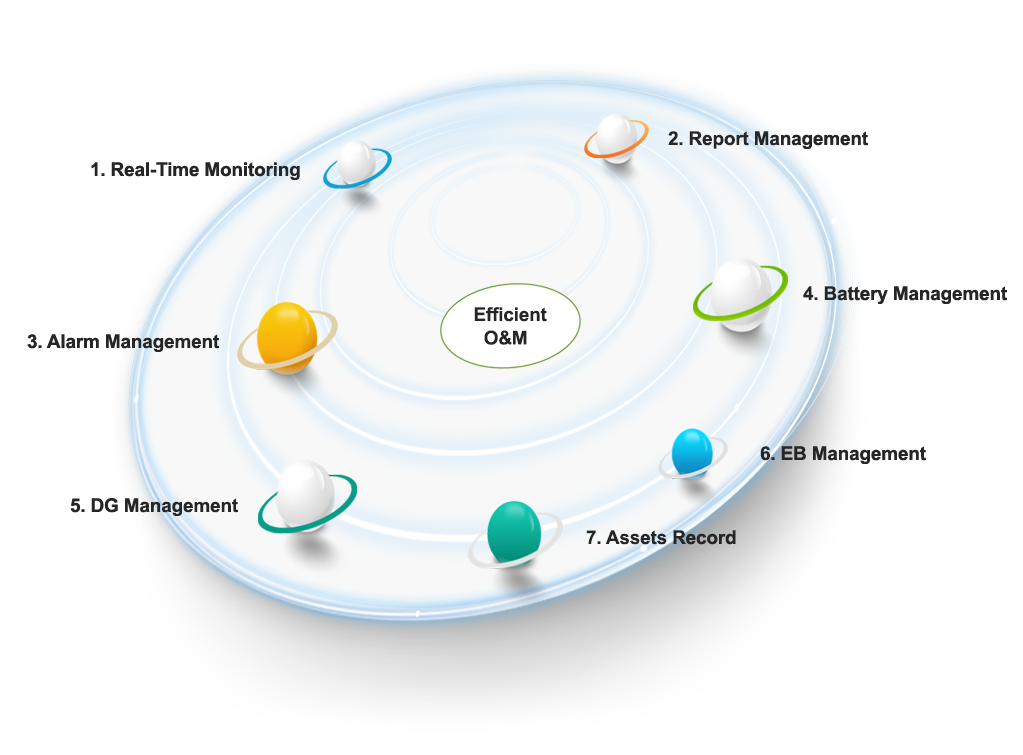
SIS-AXS Remote Monitoring & Energy Management
Why Remote Monitoring System?
Site Management
1. Effective Resource allocation
2. Equipment performance history
3. Inventory Records
Failure Management
1. Early fault identification
2. Site up status and nature of faults
3. Remote Intervention
Equipment Evaluation
1. Site Battery condition
2. DG battery condition
3. Site temperature
Energy Management
1. DG Energy
2. EB Energy
3. Battery Energy
Billing (Optional)
1. Diesel Supplies
2. Grid consumption
Scope of a Remote Monitoring System
Basic Information
Detailed Parameter Monitoring
Remote Operation
DC Energy Metering Customers wise
Fuel monitoring
Why SIS-AXS System?
1. Site Management
Effective Resource allocation
Equipment performance history
Inventory Records
2. Failure Management
Early fault identification
Site up status and nature of faults
Remote Intervention
3. Equipment Evaluation
Site Battery condition
Site temperature
Site temperature
4. Energy Management
Solar Energy
EB Energy, Battery Energy
DG Energy (Optional)
Prerequisites:
- For Software:-
- - SIS-AXS is a web based solution and customer will require any browser with Internet connectivity to access the solution.
- - All latest version of browsers are supported on PC, Mac, Android and iOS devices.
- - Android Device (optional), for optimized monitoring using Android Application.
- Hardware:-
- - Hardware Requirement at every site that needs to be remotely accessed.
- - System Infra Solutions Automation Controller (works with any make PIU/AMF/IPMS).
- - System Infra Solutions GPRS Kit
- - GPRS enabled SIM for the site
- Backend Information (Maintained by System Infra Solutions)
- - System Infra Solutions maintains the backend servers and its software on Cloud Based Infrastructure over the Internet.
- - Linux based Server
- - Third party Service used for SMS Gateway
SIS AXS: Management Expert
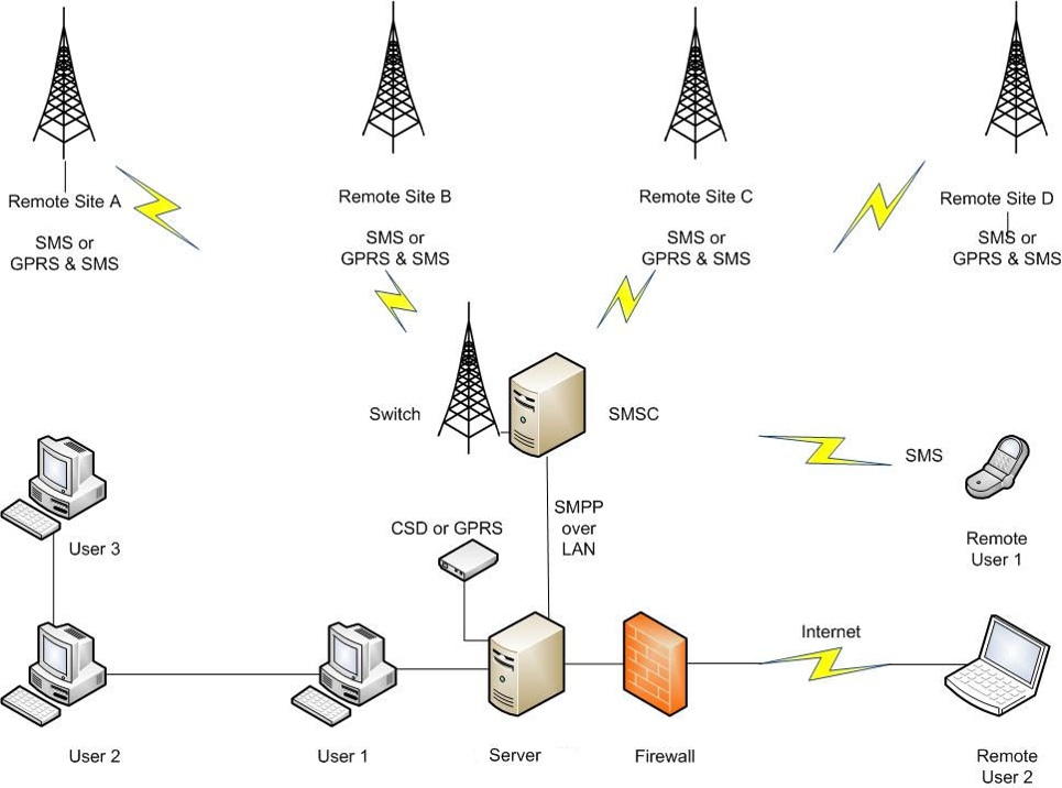
System Architecture
SIS-AXS Site Details
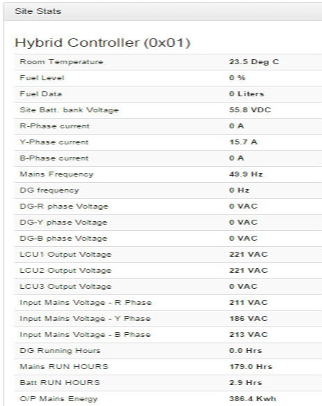
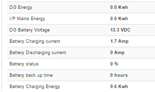
SIS-AXS Live Details
SIS-AXS Equipment Details
SIS-AXS Energy Status One Day

SIS-AXS Energy Status One Week
SIS-AXS Energy Status One Month