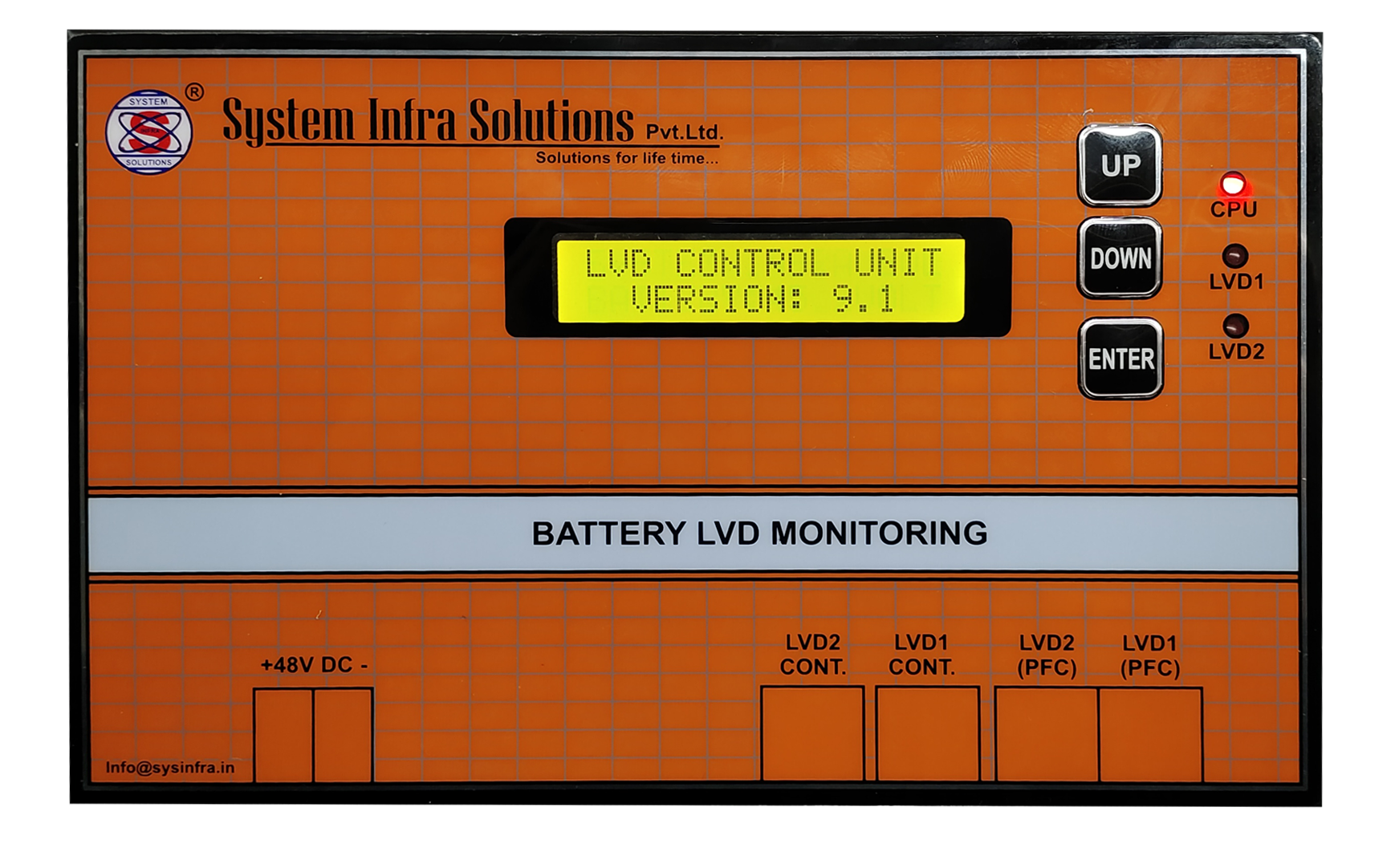
SISPL controller is an integrated multifunction high speed micro controller-based Battery LVD (Low Voltage disconnect) system. It’s having a provision of Monitoring for battery voltage.
Specification (Features)
The specification of SISPL Controller is given below.
- Monitoring of Battery bank voltage.
- Configurations of battery level voltage.
- Calibration On site facility of battery voltage.
- LVD level Alarms with potential free contact.
- High MTBF
- Compact and Modular Design.
Alarms of Potential free contact.
- LVD1 Trip.
- LVD2 Trip
LVD/Latch Controller
Configuration (Programmable Parameters)
The configuration for controller module is as follows:-
| S.NO | Parameter Name | Max Value | Min Value | Default Value |
|---|---|---|---|---|
| 1 | LVD1 Cut off | 60.0 | 20.0 | 44.0Volt |
| 2 | LVD1 Cut in | 60.0 | 20.0 | 45.0Volt |
| 3 | LVD1 Cut off | 60.0 | 20.0 | 42.0Volt |
| 4 | LVD1 Cut in | 60.0 | 20.0 | 43.0Volt |
Calibration Parameter
The calibration parameters are as follows:-
| S.NO | Parameter Name | Actual value | Measured value |
|---|---|---|---|
| 1 | Solar array Current | XXX.X | XXX.X |
Actual values display what have you apply and measured value is measurement by controller.
Calibration Parameter
The calibration parameters are as follows.
| S.NO | Parameter Name | Actual value | Measured value |
|---|---|---|---|
| 1 | Main Voltage | XXX | XXX |
| 2 | AC#1 Load current | XX.X | XX.X |
| 3 | AC#2 Load current | XX.X | XX.X |
| 4 | Room Temperature | XX.X | XX.X |
Actual values display what have you apply and measured value is measurement by controller.
Operation
Three operation of SISPL controller is given below :-
- Key function
- Calibrations
- Configurations
- LVD Operation
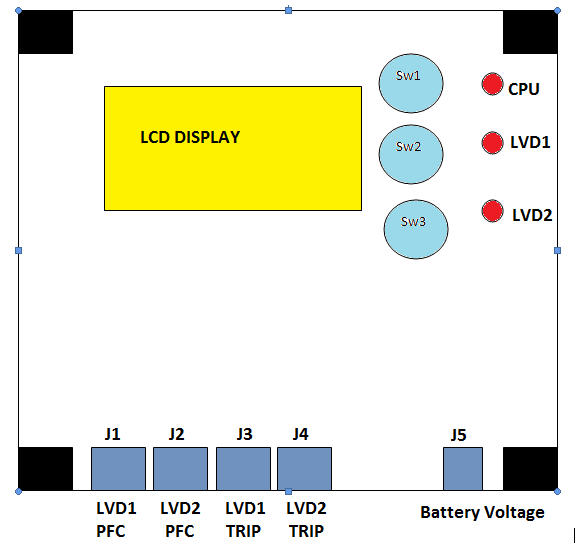
There are three switches in Display Board:-
- # SW1 for Increment
- # SW2 for Decrement
- # SW3 for Enter
1. #SW1:
When you go for configuration that time this switch working for increment.
2. #SW2:
When you go for configuration that time this switch working for decrement.
3. #SW3:
When you go for configuration that time this switch working for enters.
Key Function
Configuration
For any programmable parameter changing you can go in menu setting by configuration mode. In configuration mode you can go for that parameter which you want to change after this you can adjust by increment and decrement key and then press enter key. Then go for escape.
Calibration
For any analog parameter calibration you can go for calibration mode by configuration. In calibration mode you can go for that parameter which you want to calibrate. After you can set the value by increment and decrement key if actual value is equal to apply value press enter key and then press the escape key. And check that parameter is ok or not.
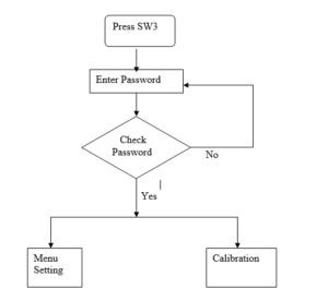
For calibration and menu setting process apply above given flow chart.
In calibration mode LCD display like this
Battery Voltage
MEASURED
XX.X (Output)
ACTUAL
XX.X (Input)
Suppose you want to calibrate Battery voltage apply Battery voltage 48.0 volt and In LCD display measured value display 25.0 and actual value is also 25.0, you can set the actual value 48.00 via INC and DEC key then press enter key. After press the enter key, After 10 seconds check the Main’s voltage display if battery voltage display 1% difference corresponding apply voltage then battery voltage calibration is OK.
LVD Operation:-
System monitor the battery voltage when battery voltage down in discharging mode up to lvd1 cut off level lvd1 is on (J3) and if voltage is continuously down up to lvd2 cut off lvd2 is on(J4).
When battery is charged battery voltage is increases up to lvd2 cut in lvd2 is off and if battery voltage is increases up to lvd1 cut in lvd1 id off. When lvd1 and lvd2 is on we generate the potential free contact corresponding J1 & J2. J5 for connected to battery voltage.