Introduction:
SIS-AXS Nano Mac controller is an integrated multifunction high speed micro controller based System.
It is having a provision of single phase/three phase mains and DG with Automatic /manual modes of operations. This controller includes protection for mains and DG (as per standards). This controller in having battery and room temperature monitoring facility. With DC Energy Meter 4 channel.
System Controller system is designed for telecom sites. It can be used Like PIU, IPMS & AMF, SISPL SIS-AXS controller unit has inbuilt Feature like remote management, Energy Management and fault detection, power scalability that enhances fuel and battery efficiency at sites. This controller follows a rational approach towards power management such as:
- Integrated AMF Function.
- AC power measurement.
- DG parameter monitoring.
- Alarm Consolidation.
- Remote monitoring facility.
- DC Energy Mater (4-CH)
The highlighting feature of SIS-AXS NANO MAC controller is that it reduces the operational costs through a well-researched fuel management system. The fault management and functionality units of this system is adaptable for Air-conditioners, Batteries, Fire alarms, Diesel Gen sets, Security, AC Power, DC power, lightening and surge protection etc.
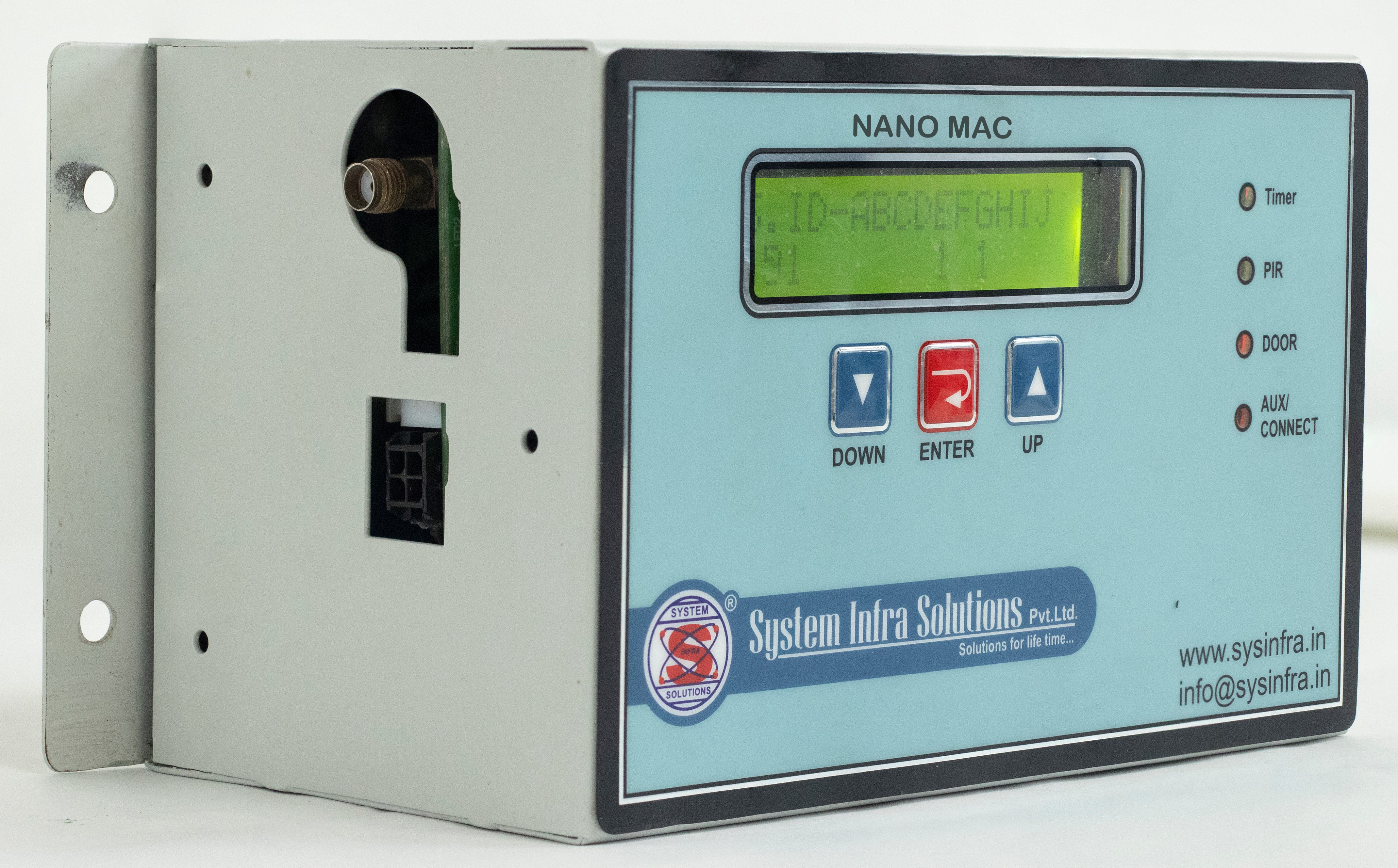
Nano Mac
Other feature:
- AC distribution unit.
- Fire Alarm module.
- Aviation lamp controller.
- Auto phase Selector.
- IPMS logic.
- SVR controller.
- Real time and events recording.
- One/Two DG control.
- Configuration (almost fifty programmable parameters).
- Calibration (on site calibration facility for all analog parameter).
Specification:
| Description | Standard Specification |
|---|---|
| Capacity | Range of 5 to 50 KVA |
| Multi Phase Logic | SIS-AXS controller will work on 1Phase, 2phase or 3Phase. Input voltage range on single phase – 145V–300V |
| Mechanical | CNC Fabricated box, using CRC Sheet duly powder coated, 1.6 mm thick CRC sheet. Split type modular design. |
| Safety | The equipment will ensure IEC 60950 safety standards |
| MTBF | All material & workmanship will be of professional quality to ensure MTBF requirement. The MTBF of the AMF controller is more than 70000 hrs. |
| Compliance | CE, Tested for safety, EMI/RFI compliance |
| Micro Controller | High-Speed micro controller True RMS for all voltage & current All the inputs to the measurement board will be duly protected against surge as per IEEE-62.41 The measurement circuit will be rated at least twice of the maximum input range, each independent for AMF & module |
| Time | Real time & date-programmable |
| Event Logs | Last 2000 events |
| RS 232t for SISPL use only | For PC interface to adjust the critical data and unload the alarms, This Port will be used for configuration of PFCs. |
| Energy | Will be able to measure the DG energy (Cumulative KWH & Hrs), Will be able to measure the EB energy (Cumulative KWH & Hrs), Will be able to measure the Battery energy (Cumulative KWH & Hrs) |
| Data Transfer | SIS-AXS controller will be equipped with suitable GPRS modem / GPRS DTU and able to process the data. |
| DG on load | After DG starts and supply is healthy |
| Blackout delay | 5 Seconds between mains and DG contactor changeover. |
| DG cooling time | 15 minutes |
| DG start attempts | Three attempts with delay between attempts ( 40 -40 -40 sec )(settable) |
| DG Lock time | After three very short mains restoration 10-10-20 minutes, DG will run for 1hrs (settable) continuously. |
| Stop Command duration | Settable from 10 to 50 seconds |
| Battery charger & DG controller unit | Automatic DG battery, SMPS charger with boost/trickle charging & with constant cur¬rent charging facility (12V) Provision of Auto manual mode selection |
| Auto Phase selector | The AMF Controller will be inbuilt with auto phase selector which will select any two phase or single phase out of 3 Phase. There will be a electrical and mechanical interlock between each contactor to avoid short circuit in case of electronic failure |
| Set point-for high temperature alarm | Factory set (“ON” at 40°C and “OFF” at ON - 3°C) |
| DG set measurements | Mains/DG status, DG accumulated hours, DG voltage, DG Energy Measurement (DG KWH) |
| Mains measurements | Input Voltage, Output voltages for line conditioning module, Mains Energy Measurement (EB KWH) |
| Battery measurements | Battery running hrs & KWH (Accumulated) |
| LED Indications: | Mains ON, DG ON, Smoke/ Fire Alarm, DG Common Fault, Fuel Low, System battery low, High Shelter temperature |
| List of potential free dry contacts | Alarms will be extended to NOC / TOC through changeover contact (both ‘NO’,
‘NC’). Mains fail, Shelter Door open/ Intruder, Low fuel level, Common fault -- LLOP/Alt fault/HCT/HWT/V belt/Dg fail to start/DG fail to stop, Smoke/Fire, Load on DG, DG Fail to stop, DG Fail to start, DG over load, Shelter high temperature, Site on battery, BTS Battery Low. |
| Standard setting | Setting in the AMF Controller can change manually & Laptop. |
| Site Calibration | All measured parameter can you calibrate through S/W on field |
| Dual DG Logic | Will be provided the Dual dg logic on sequential basis. |
Configuration (Programmable Parameters)
The configuration for controller module is as follows :-
| S.NO | Parameter Name | Max Value | Min Value | Default Value |
|---|---|---|---|---|
| 1 | MAINS HIGH CUTOFF | 500 | 240 | 300 |
| 2 | MAINS LOW CUTOFF | 350 | 70 | 90 |
| 3 | MAINS HIGH CUTIN | 500 | 220 | 290 |
| 4 | MAINS LOW CUTIN | 360 | 70 | 130 |
| 5 | DG HIGH CUTOFF | 280 | 240 | 260 |
| 6 | DG LOW CUTOFF | 210 | 140 | 170 |
| 7 | DG RPM HIGH | 3000 | 1550 | 1650 |
| 8 | DG RPM LOW | 1500 | 1000 | 1350 |
| 9 | ROOM TMP.HIGH ALARM | 60 | 15 | 40 |
| 10 | DG CRANK TEMP HIGH | 60 | 15 | 35 |
| 11 | DG OVERLOAD | 150 | 1 | 35 |
| 12 | EB OVERLOAD | 150 | 1 | 35 |
| 13 | BTS BATTERY LOW | 60.0 | 20.0 | 47.0 |
| 14 | DG AUTO RUN TIME | 18 | 1 | 6 |
| 15 | CRANK ACTIVE TIME | 10 | 1 | 3 |
| 16 | CRANK RETRIES | 5 | 0 | 2 |
| 17 | STOP HOLD TIME | 50 | 10 | 30 |
| 18 | STOP RETRIES | 5 | 0 | 2 |
| 19 | DG WARM UP TIME | 90 | 10 | 10 |
| 20 | MAINS RESTORE TIME | 300 | 20 | 30 |
| 21 | DG COOL DOWN TIME | 900 | 30 | 60 |
| 22 | DG LOCK TIME | 150 | 10 | 60 |
| 23 | LLOP DELAY TIME | 50 | 5 | 5 |
| 24 | DG START INTERVAL | 240 | 30 | 40 |
| 25 | CT RATIO | 250 | 25 | 125 |
| 26 | LLOP ENABLE/DISABLE | DISABLE | ||
| 27 | EB FLUCTION TIME | 30 | 1 | 20 |
| 28 | EQUALIZE CHG NORMAL | 0 | 0 | DISABLE |
| 29 | EQUALIZE CHG MANNUALY | DISABLE | ||
| 30 | BATTERY CHARGE INTERVAL | 1440 | 1 | 168 |
| 31 | BATTERY CHARGE TIME | 48 | 1 | 12 |
| 32 | AVIATION ON TIME IN HOUR | 23 | 0 | 18 |
| 33 | AVIATION ON TIME IN MINUTE | 59 | 0 | 0 |
| 34 | AVIATION OFF TIME IN HOUR | 23 | 0 | 6 |
| 35 | AVIATION OFF TIME IN MINUTE | 59 | 0 | 0 |
| 36 | SVR HIGH CUTOFF | 300 | 240 | 260 |
| 37 | SVR LOW CUTOFF | 210 | 150 | 180 |
| 38 | PSEL ENABLE/DISABLE | ENABLE | ||
| 39 | PSEL HIGH CUT OFF | 300 | 240 | 300 |
| 40 | PSEL LOW CUT OFF | 180 | 70 | 90 |
| 41 | PSEL HIGH CUTIN | 290 | 250 | 280 |
| 42 | PSEL LOW CUTIN | 20 | 70 | 120 |
| 43 | PHASE UNBALANCE | 90 | 20 | 50 |
Calibration Parameter
The calibration parameters are as follows:-
| S.NO | Parameter Name | Actual value | Measured value |
|---|---|---|---|
| 1 | Main R-PH Voltage | xxx | xxx |
| 2 | Main Y-PH Voltage | xxx | xxx |
| 3 | Main B-PH Voltage | xxx | xxx |
| 4 | LCU#1 Voltage | xxx | xxx |
| 5 | LCU#2 Voltage | xxx | xxx |
| 6 | LCU#3 Voltage | xxx | xxx |
| 7 | DG R-PH Voltage | xxx | xxx |
| 8 | DG Y-PH Voltage | xxx | xxx |
| 9 | DG B-PH Voltage | xxx | xxx |
| 10 | EB I/P current R-Phase | xxx | xxx |
| 11 | EB I/P current Y-Phase | xxx | xxx |
| 12 | EB I/P current B-Phase | xxx | xxx |
| 13 | O/P current R-Phase | xxx | xxx |
| 14 | O/P current Y-Phase | xxx | xxx |
| 15 | O/P current B-Phase | xxx | xxx |
| 16 | Room Temperature | xxx | xxx |
| 17 | Ambient Temperature | xxx | xxx |
| 18 | BTS Battery voltage | xxx | xxx |
| 19 | DG Battery voltage | xxx | xxx |
Product Technology Edge
Cutting Edge Software Integration:
- App based solution with real time updates.
- In-House Development with R&D capability for future supports
State of the Art Hardware System:
- Customized Electronic Hardware developed with Remote Access thru Mobile APP
- In-house Developed & Upgraded Phasewise with customization to telecom needs
Server Support:
- Self made Linux based Server especially for telecom site
- In-House Developed Auto Dialler for event specific L-1,L-2 Calling.
- Access to 200 Log file Data on App .More Available on demand.
Advanced AI inbuild telecom site
1- Battery Bank / Cell Failure Detection
- Analyzing data for symptoms of Battery or Cell Failure
- Timely replacement will ensure better uptime of the whole site
2-Wiring Problem Detection
- Analyzing data for wiring related issues
- Pin point incorrectly wired or disconnected wiring
- Incorrect wiring leads to faulty or no data
- Fixing them will ensure early warning systems are in place
3-Automation Failure Detection
- Site Automation is the heart of a healthy and productive site
- Automation of the Site is analysed and detected if running in Manual mode
- Such failure causes excessive fuel usage
- Fixing this issue will decrease cost of running the site
4-BTS Voltage
- BTS voltage is the main lifeline parameter of a healthy site
- Analyse pattern associated with this parameter
- Identifies weak sites that frequently reach dangerous levels of BTS voltage
- Timely intervention on such sites can improve uptime
5-Physical Access
- Theft Alarm Analysis
- Analyse pattern associated with physical access of the Tower
- Can flag if tower is used in unauthorised manner
6-Temperature
- High temperature can lead to failure of the site
- Analyse pattern associated with temperature and flags if anything is of concern
Data Analytics and Intelligence xxxx site
03-March-2020 to 05-May-2020
| SR. No | Site Name | Site ID | Duration | Week | Door Open | Motion | BTS Low ( less than 48vlt) | Less than 45 vlt | Theft | HRT more than 40vlt | Smoke |
|---|---|---|---|---|---|---|---|---|---|---|---|
| 1. | xx | xxx | 3-March-20 to 10-March-20 | Week1 | 10 | 27 | 60 | 8 | 0 | 0 | 0 |
| 2. | xxx | xxx | 11-March-20 to 17-March-20 | Week2 | 52 | 61 | 43 | 0 | 0 | 0 | 0 |
| 3. | xxx | xxx | 18-March-20 to 24-March-20 | Week3 | 9 | 12 | 57 | 0 | 0 | 0 | 0 |
| 4. | xxx | xxx | 25-March-20 to 31-March-20 | Week4 | 9 | 8 | 46 | 0 | 0 | 0 | 0 |
| 5. | xxx | xxx | 9-Apr-20 to 15-Apr-20 | Week-5 | 16 | 12 | 85 | 0 | 0 | 0 | 0 |
| 6. | xxx | xxx | 16-Apr-20 to 22-Apr-20 | week-6 | 7 | 11 | 98 | 6 | 0 | 0 | 0 |
| 7. | xxx | xxx | 23-Apr-20 to 29-Apr-20 | week-7 | 31 | 24 | 127 | 4 | 0 | 0 | 0 |
| 8. | xxx | xxx | 30-Apr-20 to 6-May-20 | week-8 | 24 | 36 | 69 | 0 | 0 | 0 | 0 |
| 9. | xxx | xxx | 07-Apr-20 to 15-May-20 | week-9 | 12 | 75 | 219 | 0 | 0 | 0 | 0 |
Data Analytics and Intelligence xxxx
20-December-2019 to 19-May-2020
| SR. No | Site Name | Site ID | Duration | Week | Door Open | Motion | BTS Low ( less than 48vlt) | Less than 45 vlt | Theft | HRT more than 40vlt | Smoke |
|---|---|---|---|---|---|---|---|---|---|---|---|
| 1. | xx | xxx | 20-Dec-19 to 31-Dec-19 | Dec-19 | 2506 | 31 | 413 | 60 | 0 | 0 | 0 |
| 2. | xxx | xxx | 01-Jan-20 to 31-Jan-20 | Jan-20 | 13228 | 109 | 1709 | 122 | 0 | 0 | 0 |
| 3. | xxx | xxx | 01-Feb-20 to 29-feb-20 | Feb-20 | 9027 | 228 | 1568 | 182 | 0 | 0 | 0 |
| 4. | xxx | xxx | 01-March-20 to 07-Mar-20 | Week1 | 2291 | 36 | 364 | 52 | 0 | 0 | 0 |
| 5. | xxx | xxx | 07-March-20 to 14-Mar-20 | Week-2 | 2524 | 16 | 390 | 27 | 0 | 0 | 0 |
| 6. | xxx | xxx | 15-March-20 to 21-Mar-20 | week-3 | 2164 | 79 | 438 | 63 | 0 | 0 | 0 |
| 7. | xxx | xxx | 22-March-20 to 28-Mar-20 | week-4 | 2728 | 38 | 396 | 31 | 0 | 0 | 0 |
| 8. | xxx | xxx | 29-March-20 to 04-Apr-20 | week-5 | 2524 | 16 | 390 | 27 | 0 | 0 | 0 |
| 9. | xxx | xxx | 07-Apr-20 to 15-May-20 | week-6 | 12 | 75 | 219 | 0 | 0 | 0 | 0 |
| 10. | xxx | xxx | 05-Apr-20 to 14-Apr-20 | week-6 | 2524 | 56 | 403 | 23 | 0 | 0 | 0 |
| 11. | xxx | xxx | 16-Apr-20 to 22-Apr-20 | week-7 | 2535 | 106 | 654 | 0 | 0 | 0 | 0 |
| 12. | xxx | xxx | 23-Apr-20 to 29-Apr-20 | week-8 | 2747 | 119 | 556 | 97 | 0 | 0 | 0 |
| 13. | xxx | xxx | 30-Apr-20 to 06-May-20 | week-9 | 2895 | 111 | 843 | 168 | 0 | 0 | 0 |
| 14. | xxx | xxx | 07-May-20 to 11-May-20 | week-10 | 1981 | 55 | 633 | 170 | 0 | 0 | 0 |
| 15. | xxx | xxx | 12-May-20 to 19-May-20 | week-11 | 2396 | 35 | 535 | 76 | 0 | 0 | 0 |