This was our answer to the Telecom BSC and MSC sites needing a full proof power backup system to manage Dual DGs alternatively or as assigned to perform, having all the time tested features of our core controller matched with higher rating switch gears according to the site needs and ratings. It is equipped to provide site automation plus remote monitoring and control features, making it fail proof for constant uptime.
It is equipped to provide site automation plus remote monitoring and control features, making it fail proof for constant uptime.
Our DUAL DG Controller is designed to support both 3Ph EB/DG as well as LCU conditioned EB inputs further selecting the healthiest Phase from the already conditioned 2Phases provided by the LCU, thereby giving the best of single Phase input to the Power Plant.
Dual DG Panel
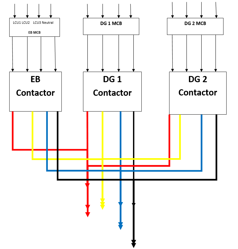
Dual DG Controller block diagram
General Features of Dual DG Controller
| Group Category | Specification | Features | |
|---|---|---|---|
| Controller | support all appended logics | Support all appended logics & conditions. Has 4 spare fault channels, 20 Event fault log (name of event, time & date at engine hours ) | |
| In Put logics of EB & DG | EB 1 Ph | DG 3 Ph | Automation, Manual logics performance with safety alarm provision |
| EB 1 Ph | DG 1 Ph | Automation, Manual logics performance with safety alarm provision | |
| EB 3 Ph | DG 1 Ph | Automation, Manual logics performance with safety alarm provision | |
| EB 3 Ph | DG 3 Ph | Automation, Manual logics performance with safety alarm provision | |
| DG Protection | DG Freq :46-65 Hz. | DG Freq :46-65 Hz. | |
| DG-LV-1Ph-180 | Auto reset | ||
| DG-OV--1Ph-260 | Auto reset | ||
| HCT/HWT | Hard reset | ||
| LLOP | Hard reset | ||
| LFL | Auto reset | ||
| Over load | Hard reset | ||
| Over speed | Hard reset | ||
| Engine fail to start | Hard reset | ||
| Fire alarm | PFC will be provided From Shelter Sensor, Site power to disconnect | ||
| Engine fail to stop | Hard reset | ||
| DG start/stop | 3 attempt start | As per settable | 1 sec delay in every crank attempt |
| 1 Attempt Stop | As per settable | field settable 20 to 50 sec | |
| DG Start / run / rest Logic (in case of EB fail & non EB) (Fuel optimizer) | Voltage DC | Below Set limit menu settable | Field settable Range - 20 -60V for 48V system |
| Voltage EB | Below Set limit - Menu settable | As per set level | |
| Temp. Shelter | More than set limit - Menu-settable | 15 - 60 Deg. C (extended temp. sensor with PFC at shelter) | |
| DG run In Hrs | Run-Menu settable | 1 to 8 Hrs (steps of range-1 Hrs.) | |
| DG rest In Hrs | Rest-Menu settable | 5 to 600 Minutes (steps of range-5 mts.) | |
| Boost Charging Mode | Menu settable interval in 1 to 1440 Hrs | Continuous Power Supply for 12 | Field Settable |
| Dry Contacts( PFC's) | HCT/HWT | ||
| LLOP | |||
| LFL | |||
| Over load | |||
| Over speed | |||
| DG Common Fault | |||
| DG Fail to Start | |||
| DG Fail to Stop | |||
| High Shelter Temp | |||
| DG On Load | From Contactor Status | ||
| Mains Fail | From Contactor Status | ||
| Fire Alarm | |||
| HMR Hard memory | DG Hours | Cumulative up to xxxxxxx.x digit (7.1 digit) | |
| Mains Duration | Cumulative up to xxxxxxx.x digit (7.1 digit) | ||
| DG Battery Charging | Static charger | Required in both mode DG and EB | |
| Emergency S/w | Required | ||
| Indicating & recording parameters (can be covered under controller display) | Required | ||
| EB - DG Voltages | Indicating | ||
| EB - DG load | Currents | ||
| EB - DG frequency | Currents | ||
| KWH | Cumulative temper proof | ||
| DG HMR | Cumulative temper proof | ||
| EB HMR | Cumulative temper proof | ||
| Visual Indication(LED) | Load on mains, Load on DG, DG failure, DG start failure, Engine overload, HCT & LLOP and Over Speed. Charging | Load on mains, Load on DG, DG failure, DG start failure, Engine overload, HCT & LLOP and Over Speed. | |
| Indicating gauges | Fuel Level indicator | ||
| High cylinder/water temperature gauge | |||
| Oil pressure gauge | |||
| Switches/Push button | Auto/Manual, Mains contractor & DG Contractor ON, engine start. | ||
| AMF bypass switch (for mains & DG supply) | |||
| Earthing Bar | Earth connection bar inside the panel, with provision of 5 to 8 holes of 8mm dia. | ||
| Cable & accessories | Power cables as per KVA rating of DG | ||
| Cable entry | 50mm dia hole with gromet -Qty-2 , 38mm dia hole with gromet- Qty 2 | ||