DC Energy Meter 4 CH
DC energy Measurement is based on the principle of integration of DC power with time incorporating State of art microprocessor-based design. DC power meters that measures the voltage, current, power and energy parameters. They are used for monitoring and controlling energy flow in DC systems. All SISPL models offers integration with external systems using MODBUS RTU protocol and an on-board RS485 serial communication port.
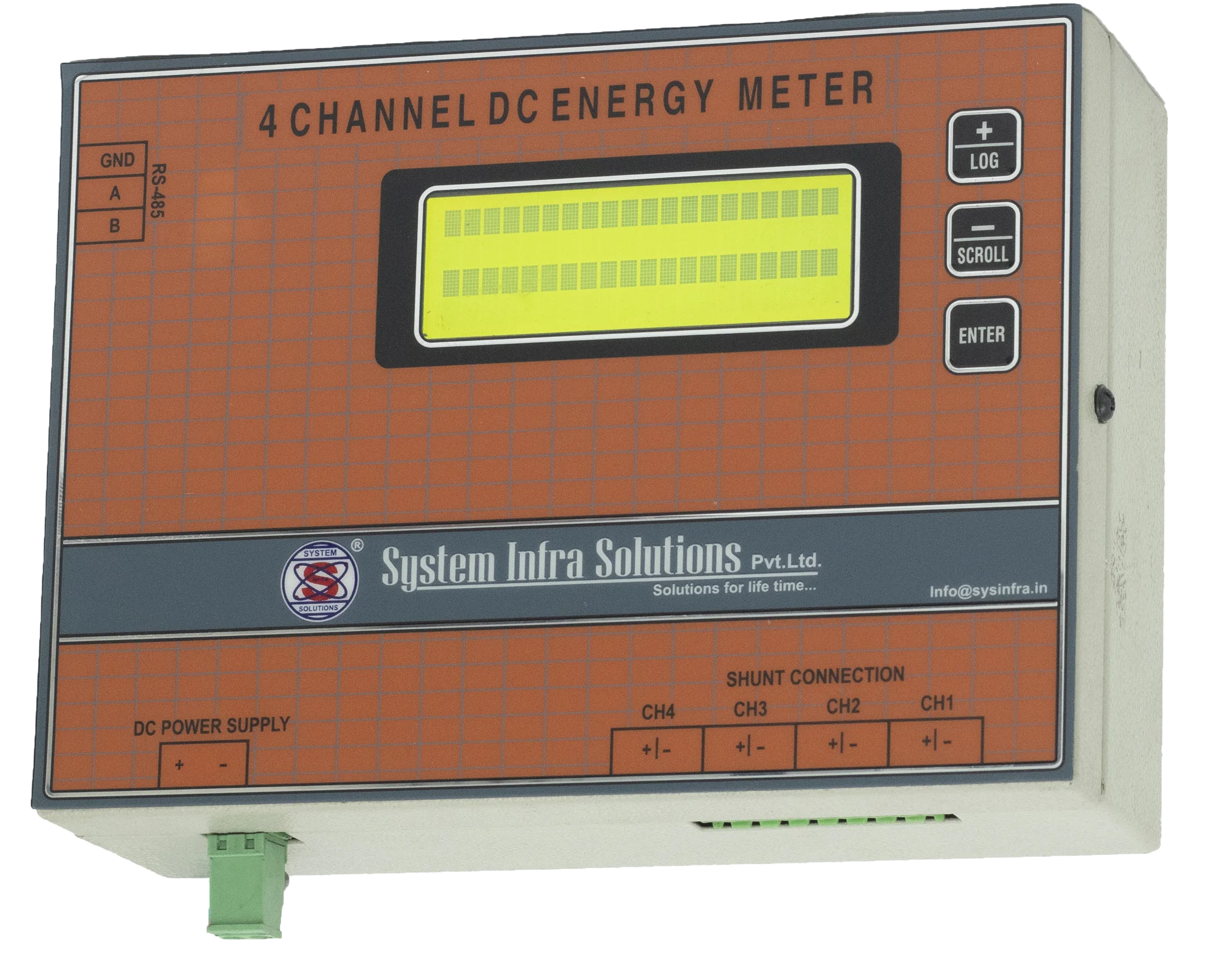
This device is capable to measure 4 Channel DC. The DC energy meter is Equipped with 20 x 4- character LCD, it displays measured values of current, voltage and energy in four channels with real time Clock. It has inbuilt Real time Clock and internal data storage memory(1MB) to create an internal Data log of measured values with real time. Our DC Energy Meter is equipped with four dc current measurement channels coupled with one DC voltage input. It measures DC Current & KWH in each channel, maintains data log of the same at preset Frequency of data updating, real time clock, Side ID. It is communicating with RS485.
( DC Energy Meter )
Salient Features:-
- Programmable & password protected.
- EEPROM based memory for Energy data.
- In built real time clock.
Product Features:-
1 Input Supply: Input supply Range- 36V to 60V
2-Measurement
Voltage Measurement: 0 Volt to 72V
Current Measurement: 0 A to 300 A
3. KWH measurement: KWH measurement – 4 channels
4. Communication: Protocol- RS485 Half duplex
RTU Baud rate: 9600.
3.1 Attached protocol: (Note – Please see protocol detail file for more details.)
4 EEPROM: 1MB
5 Flexibility: This device is flexible to measure current using different rating of hall effect CT with some calibration.
Calibration: Voltage and current can be calibrate.
Accuracy: ± 2% (depend on CT)
Response time: ess than 500 ms.
Mounting type. DIN RAIL
Response time Less than 500 ms
Flexibility: This device is flexible to measure current using different rating of hall effect CT with some calibration.
Channels: 4 channels.
Measurement: Voltage, current, KWH.
Systems Clock: Real Time Clock on Board.
Display 4 Line 20 Character LCD Display.
Default ID Value 0 t0 31, Default -0
Device ID
Dimensions 10 Character (xyx……..)
1)- Press ENTER key
2)-Three available options
a)- Setting
b)- meter Matching
c)- Log View
7.1- Setting Option
a)- Site ID- can vary using UP and DOWN Key
b)- Device ID- can vary using UP and DOWN Key
c)- RTC setting
7.2- Measurement Matching
a)- Channel 1 Current matching
b)- Channel 2 Current matching
c)- Channel 3 Current matching
d)- Channel 4 Current matching
e)- Voltage matching
f)- Channel 1 Current Reference matching
g)- Channel 2 Current Reference matching
h)- Channel 3 Current Reference matching
i)- Channel 4 Current Reference matching
* note Reference can be matched only on no Load
7.3 Log View
Recorded log can be viewed in Log View.
8)- Display and Buttons
20x4 LCD Display
No of buttons - 3
DC Energy Meter Specification
Measurement of parameter:-
| S.NO | Parameter | Value/Requirement |
|---|---|---|
| 1 | DC Voltage | 1 Channel |
| 2 | DC Current | 4 Channel |
| 3 | DC Supply | From Rectifier DC Voltage |
Range of Measurement of parameter
| S.NO | Parameter | Range |
|---|---|---|
| 1 | DC Voltage | 20-60 V dc |
| 2 | DC supply | 0-200A dc |
Resolution of Measurement of parameter
| S.NO | Parameter | Resolution |
|---|---|---|
| 1 | DC Voltage | 0.1V |
| 2 | DC supply | 0.2A |
Measurement Input Method
| S.NO | Parameter | Method |
|---|---|---|
| 1 | DC Voltage | 2 pin direct input connection to rectifier output |
| 2 | DC supply | 2Pin/channel, Voltage drop across shunt common negative with rectifier voltage |
Measurement Accuracy
| S.NO | Parameter | Accuracy |
|---|---|---|
| 1 | DC Voltage | 1%FSR@ 25 degree C |
| 2 | DC supply | 1%FSR@ 25 degree C |
Parameter Measurement Method
| S.NO | Parameter | Method |
|---|---|---|
| 1 | Input | Differential Input with drift compensation current |
| 2 | Data Acquisition | Multiplexed |
Derived Parameter
| S.NO | Parameter | Unit |
|---|---|---|
| 1 | Power | Kw |
| 2 | Energy | Kwh |
Range of Derived Parameter
| S.NO | Parameter | Range |
|---|---|---|
| 1 | Power | 0-50Kw |
| 2 | Energy | 0-9999999.9 Kwh |
Display Resolution of Derived Parameter
| S.NO | Parameter | Resolution |
|---|---|---|
| 1 | Power | 0.1Kw |
| 2 | Energy | 0.1Kwh |
Accuracy of Derived Parameter
| S.NO | Parameter | Accuracy |
|---|---|---|
| 1 | Power | 1%FSR@ 25 degree C |
| 2 | Energy | 1%FSR@ 25 degree C |
Display Parameter
| S.NO | Parameter | Description |
|---|---|---|
| 1 | Cumulative Energy | Ampere, power & Energy per channel per screen |
| 2 | Power | Ampere, power & Energy per channel per screen |
| 3 | Ampere | Ampere, power & Energy per channel per screen |
| 4 | Voltage | Common Rectifier Voltage |
| 5 | Daily Log | Consumed Energy per day with date & Time of all four channel |
| 6 | Monthly Log | Consumed Energy per month with date & Time of all four channel |
Range of Editable Parameter
| S.NO | Parameter | Range |
|---|---|---|
| 1 | Shunt | 1-99mV,1-200 amp |
| 2 | Slave Id | 1-256 |
| 3 | RTC | Real time clock setting |
Inbuilt protection for rugged telecom Application
| S.NO | Parameter | Protection |
|---|---|---|
| 1 | Voltage | Voltage rating & reverse polarity |
| 2 | Current | Up to 60V |
| 3 | Serial port | Serial port |
| 4 | Editable Parameter | Accessible only with password |
| 5 | Cumulative Energy | Stored & Increment in Memory |
Termination Connector on DCEM
| S.NO | Parameter | Protection |
|---|---|---|
| 1 | Measurement port & supply port | Suitable for Voltage & Current |
| 2 | Serial port RS-485 | 3PIN Male Female |
| 3 | Voltage & Current rating | 300V/10A |
| 4 | Connection marking | Non Erasable ink with Channel Input marking, Voltage Marking with( +/-) & Serial Port RS-485 (A/B/GND) Marking |
Internal Details of DCEM Critical Components/Software Inputs
| S.NO | Parameter | Details |
|---|---|---|
| 1 | Front Screen Display | 4×20 Alphanumeric LCD |
| 2 | Memory | Serial EEPROM 256 K |
| 3 | Memory Life | 20 Years |
| 4 | RTC( Real time Clock) | High Accuracy with 60 deg C |
| 5 | Update of DCEM Memory | Every 0.1 kwh Increment |
| 6 | Power supply | Approx 2 watts |
Environment & General Specifications
| S.NO | Operating Condition | Details |
|---|---|---|
| 1 | Operation Temperature | 0-60 degree C |
| 2 | Storage Temperature | -20 to 80 degree C |
| 3 | Humidity | 0-80% |
| 4 | Mounting | Wall mountable |
Details of Serial Rs-485 Communication Port
| S.NO | Communication part | Details |
|---|---|---|
| 1 | Protocol | 1 /2 Duplex Mod Bus protocol |
| 2 | Setting-1 | Default Slave id 1, Function code 3, Baud rate 9600 |
| 3 | Setting-2 | 1 stop bit, No parity, Start address 30000 |
| 4 | Interface | A, B, GND ( DX-, DX+, GND) |
| 5 | Isolation | 4KV |
| 6 | Device/ Unit address | 01-256 |
Data Type & address for data reading
| S.NO | Data | Type |
|---|---|---|
| 1 | Energy | Float |
| 2 | Amp | Float |
| 3 | Voltage | Float |
| 4 | Starting address 30000 | Channel #1 Energy |
| 5 | Starting address 30002 | Channel #1 Current |
| 6 | Starting address 30004 | Channel #2 Energy |
| 7 | Starting address 30006 | Channel #2 Current |
| 8 | Starting address 30008 | Channel #3 Energy |
| 9 | Starting address 30010 | Channel #3 Energy |
| 10 | Starting address 30012 | Channel #4 Energy |
| 11 | Starting address 30014 | Channel #4 Energy |
| 12 | Starting address 30016 | Voltage |