This rack mountable compact smart device covering 1U 19” standard rack space, is designed to sense and generate alarms, commonly encountered at a telecom site. The unique design of the RMS was specifically developed for a renowned PSU as per their unique specification. The main requirements were to provide a missing interface in their existing Infra rendered useless by the aging equipment. Although a customised solution to act as the heart of the Remote Monitoring, it’s much useful to everyone facing similar challenges due to their aging equipment’s and reap all the benefits of our R&D team’s research backed by the clients valuable feedback.
RMS is built on our high speed micro controller based platform, which has proven it’s worth at the challenging conditions of remote telecom sites.
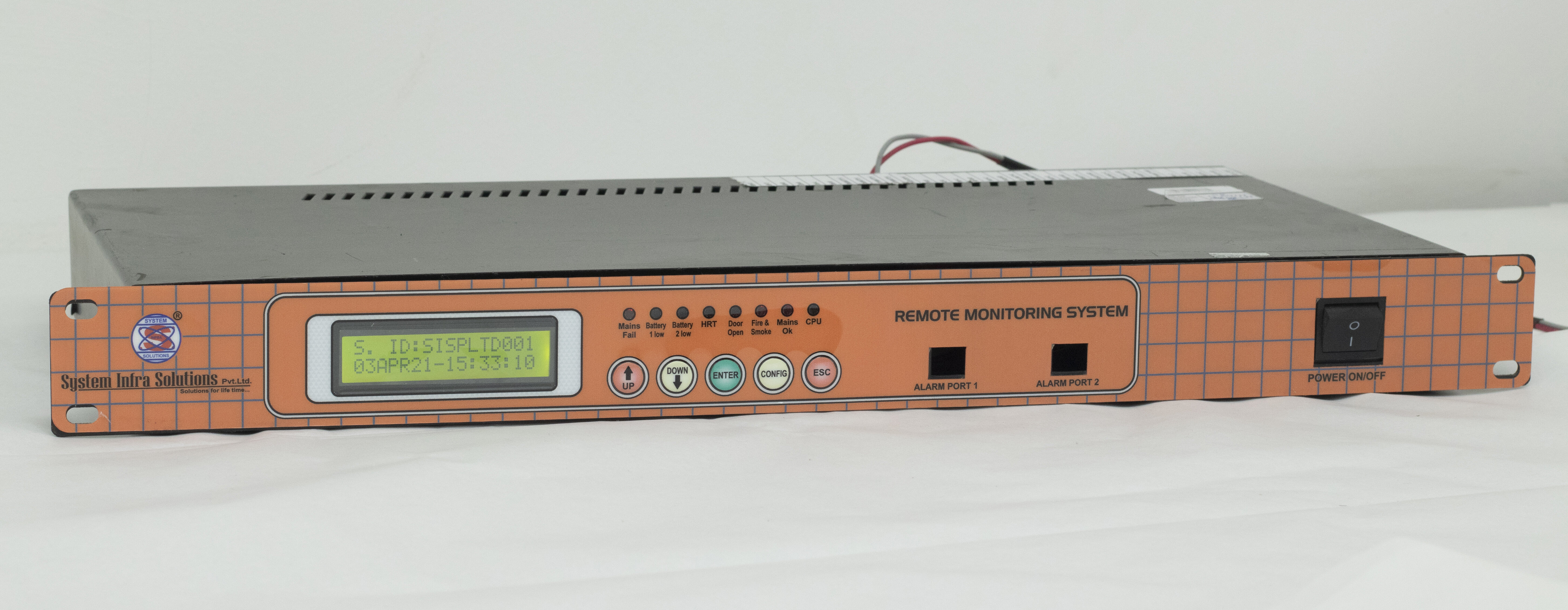
( Remote Monitoring Controller System )
System feature:-
The specification of SISPL Controller is given below.
- Monitoring of Main’s (Three/single) Phase Voltage, Current, Frequency, Run Hours and Energy.
- Monitoring of Grid Voltage, Current, Run Hours and Energy.
- Monitoring of Battery bank voltage, current, status (SOC) and energy.
- Monitoring Room temperature
- Configurations of all critical parameter.
- Calibration (On site Calibration facility for all Analog Parameter).
- Smoke / Fire Alarm.
- Fault Alarms with Free of potential.
- Real Time and Events Recording.
- Real time monitoring through GPRS communications.
- High MTBF
- Compact and Modular Design.
Alarms of Potential free contact.
- Main’s Fail.
- Main’s OK
- Smoke Fire.
- Grid array voltage high.
- High Room Temperature.
- Grid array voltage low.
- Battery low
- Door open.
- Solar Theft.
Features of RMS Alarm ( Specification)
| S.NO | Parameter |
|---|---|
| 1 | High speed Micro-controller |
| 2 | Upto 12 sensing. |
| 3 | Power Consumption < 5W. |
| 4 | Mains fail alarm. |
| 5 | Smoke fire alarm. |
| 6 | DG battery low alarm. |
| 7 | Room temperature high alarm. |
| 8 | Rectifier fail alarm. |
| 9 | DG - ON- Load alarm. |
| 10 | BTS battery low alarm. |
| 11 | Low fuel level alarm. |
| 12 | Phase fail alarm. |
| 13 | + 3 spare alarms for future use. |
| 14 | Calibration option is there |
| 15 | Password change option is there for security purpose |
| 16 | LED’s for Alarm and status representation. |
| 17 | 20x4 LCD & five Push buttons for user interface. |
| 18 | Size : 480x220x45 mm |
| 19 | Weight- 3.5kg |
Relays for Alarms
Mains fail, Smoke/ fire, DG battery low, Room temperature high, Rectifier fail, DG - ON- Load, BTS battery low, Low fuel level, Phase fail
2 Switches
Power ON/OFF, Smoke/Fire Activate/Deactivate
Future Proof
Has 4 additional relays for future sensing, Has an in-build programing switch for future up-gradations
Additional features can be integrated
- AC measurement card
Ease of use
Display 2x16, Easy input buttons
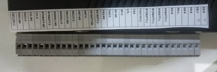
Wire connection of RMS
| Input Connection | Output connection |
|---|---|
| Mains R-Phase | Mains Fail common |
| Mains Y-Phase | Mains Fail (NO) |
| Mains B-Phase | Smoke/Fire common |
| Mains Neutral | Smoke/Fire (NO) |
| DG Phase | DG Battery Low common |
| DG Neutral | DG Battery Low (NO) |
| DG Battery (+ve) | Room Temperature common |
| DG Battery (-ve) | Room Temperature (NO) |
| Input Connection | Output connection |
|---|---|
| Battery Bank (+ve) | Rectifier Fail common |
| Battery Bank (-ve) | Rectifier Fail (NO) |
| Rectifier SMPS PP (+ve) | DG on Load common |
| Rectifier SMPS PP (-ve) | DG on Load (NO) |
| GROUND | Battery Bank Low common |
| Smoke/Fire input | Battery Bank Low (NO) |
| Low DG Fuel input | Low DG Fuel (NO) |
| Smoke/Fire (Power Supply) |
Test Report
 Efficiency Test Report
Heat Run Test Report
Functional Test Report
IR & HV test report
Measurement Parameter Test
Connection
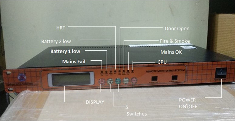
Key Function
# SW1 for Increment and Reset, # SW2 for Decrement and Scrolling, # SW3 for Enter and Events, # SW4 for Configuration, # SW5 for Escape
Key Function Description:-
#SW1:
This switch is used for two purposes one for increment and other for system reset.
Normally this switch is working for system reset. When you go for configuration that time this switch working for increment.
#SW2:
This switch is used for two purposes one for decrement and other for display scrolling. Normally this switch is working for display scrolling. When you go for configuration that time this switch working for decrement.
#SW3 :
This switch is used for two purposes one for Enter and other for events log display. Normally this switch is working for events log display. When you go for configuration that time this switch working for enters.
#SW4:
This switch is used for two purposes one for menu decrement and other for configuration normally this switch is working for configuration. When you go for configuration that time this switch working for menu decrement.
#SW5:
This switch is used for escape. Purpose of this switch in any stage you can go for default display.